Introduction
In this part of the course we will enter into the third dimension! We’ll find out what math stays behind it to get the 3D effect on a flat surface of a screen and then we will use this knowledge to create a colored pyramid. In this section, I will not place the whole code, but I will point and discuss the places that have changed from the previous part. VC ++ 2010 solution can be downloaded from here. Let’s get started!
Theory
To be able to understand what is really going on in the code, we must first look at the math – the transformation of vertex data (mainly their positions) to different coordinate spaces. This may sound strange, but in practice it’s quite easy.
Set of transformations
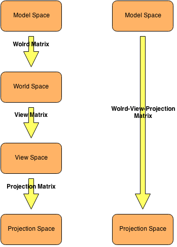
Each position and direction in the 3D world belongs to a coordinate system. To move a position/direction to another system we need to use a transformation matrix (matrices dimensions are 4×4). The most popular matrices in computer graphics programming are: world, view and projection. The following diagram shows a standard set of transformations that operate on the three-dimensional geometry.
As we can see, to move from one space to another, simply multiply the vector of position/direction of the geometry by the corresponding matrix. It’s important to fully understand these spaces to be able to freely use them.
Local (model) space
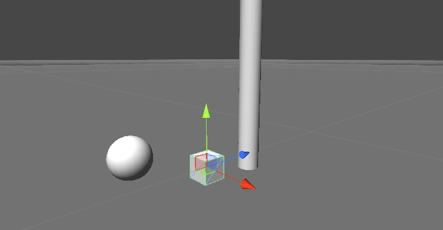
It is constructed from the raw data of the positions of vertices for a specific geometry (mesh), which have not been modified in any way. These data mostly come from a tool for creating 3D models (Maya, 3DS Max, Blender).
World space
The coordinates of the vertices are now in the world space (our 3D scene). When we multiply vertices that are in the local area by the world matrix we get transformed vertices (their positions) in the world space (scene). These positions are particularly important when want to move objects around the scene or when we want to perform some light calculations in shaders.
View (camera) space
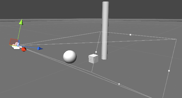
The coordinates in this space are the coordinates in the view frustum. The positions of vertices (and other vertices data) are set relative to the virtual camera (eye) through which we can see the created scene. To get to this space we must multiply vertices’ positions in the world space by a view matrix.
Projection (homogenous) space
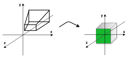
When we multiply a view matrix by a projection matrix, then the camera’s view frustum (truncated pyramid) is transformed into a cube. During this transformation, we can consider the ratio of the width to the height of the screen ( aspect ratio) and the view angle. The result of this transformation is a 3D image on a flat screen with the impression of depth, perspective (objects closer to the camera are larger and farther objects are smaller). Moreover, this transformation also culls geometry, which is outside the two planes of view frustum ( near and far planes). The area that we see on the screen is market with green in the picture below.
Below is the final image (area highlighted with green in the picture above):
One of the main purposes of vertex shader is to transform the vertex positions to projection space. This can be done in such a way that to a shader we send matrices (world, view and projection) and make there three multiplications by the position of a vertex. You can of course optimize it to offload graphics processor. To this end, we multiply the world, view and projection matrices in the program that runs on CPU and the result matrix is saved in a separate variable (called WVP matrix), which is then sent to a Vertex Shader. Thus, the amount of data that is sent to a GPU and the amount of computation is lesser and GPU can use this free computational power to compute something else.
Explanation of code
After a theoretical introduction, we may have a question like: “Everything is good with these matrices, but how do I create them?”. GLM library comes with the aid, which do all the stuff with matrices (from mathematical point of view) and we do not even need to know how to these matrices should look like (except that they are 4×4 matrices). However, if someone is interested in how these matrices are constructed, you can check this information on the Internet.
Well, let’s look at the application code now. We want to go now into the third dimension and we would like to draw a pyramid. For this purpose we need to update array of vertices:
GLuint programHandle = NULL;

glm::vec3 vertices [] = {glm::vec3 (-0.5 f,-0.5 f, 0.5 f), //basis
                         glm::vec3 (0.5 f,-0.5 f, 0.5 f),
                         glm::vec3 (0.5 f,-0.5 f,-0.5 f),
                         glm::vec3 (-0.5 f,-0.5 f, 0.5 f),
                         glm::vec3 (0.5 f,-0.5 f,-0.5 f),
                         glm::vec3 (-0.5 f,-0.5 f,-0.5 f),

                         glm::vec3 (-0.5 f,-0.5 f,-0.5 f), //left side
                         glm::vec3 (-0.5 f,-0.5 f, 0.5 f),
                         glm::vec3 (0 .0F, 0.5 f, 0 .0F),

                         glm::vec3 (0.5 f,-0.5 f, 0.5 f), //right side
                         glm::vec3 (0.5 f,-0.5 f,-0.5 f),
                         glm::vec3 (0 .0F, 0.5 f, 0 .0F),

                         glm::vec3 (-0.5 f,-0.5 f, 0.5 f), //front side
                         glm::vec3 (0.5 f,-0.5 f, 0.5 f),
                         glm::vec3 (0 .0F, 0.5 f, 0 .0F),

                         glm::vec3 (0.5 f,-0.5 f,-0.5 f), //back side
                         glm::vec3 (-0.5 f,-0.5 f,-0.5 f),
                         glm::vec3 (0 .0F, 0.5 f, 0 .0F)};
As we can see, the basis consists of two triangles (square), and therefore it has defined 6 vertices. However, all the side walls are triangles, hence the 3 vertices for each wall. I would recommend to draw this on a sheet in the ordinary coordinate system (Z-axis points “out” of the screen). Note the order of vertices – are served in the counter clockwise manner. This is because that by default OpenGL is set to recognize such polygons as those that are front facing virtual camera (back faces are not rendered in order to optimize drawing – culling). If you want to treat OpenGL polygons with vertices that are in the clockwise order we need to call the function glFrontFace(GLenum mode) with a parameter GL_CW.
Let’s update glDrawArrays() call in the render() to make sure that OpenGL will draw a good number of vertices:
/* Draw our object */
glDrawArrays (GL_TRIANGLES, 0, 3, 6);
Further changes occurred in the function int loadContent():
/* Set the world matrix to the identity matrix */
glm::mat4 world = glm::mat4 (1 .0F);

/* Set the view matrix */
glm::mat4 view = glm::lookAt (glm::vec3 (1.5 f 0.0 f, 1.5 f),   //camera position in world space
                              glm::vec3 (0 .0F, 0 .0F, 0 .0F),  //at this point the camera is looking at
                              glm::vec3 (0 .0F, 1 .0F, 0 .0F)); //the head is up

/* Set the projection matrix */
int w;
int h;
glfwGetWindowSize (window, &w, &h);

glm::mat4 projection = glm::perspective (45.0f, (float)w/(float)h, 0.001f, 50.0f);

/* Set MVP matrix */
glm::mat4 WVP = projection * view * world;

/* Get the uniform location and send MVP matrix there */
GLuint wvpLoc = glGetUniformLocation(programHandle, "wvp");
glUniformMatrix4fv(wvpLoc, 1, GL_FALSE, &WVP[0][0]);
In the line #2 we define the world matrix for our pyramid. The constructor glm::mat4(1.0f) creates the identity matrix (on the diagonal are 1.0, and the rest are 0.0). It has the property that when we multiply identity matrix by a matrix B as a result we get unchanged matrix B.
In the #5 line, we create a view (camera) matrix. The glm::lookAt(…), takes three vectors. The first is the position of the camera in the world. The second is the point in the world at which the camera looks. The third vector tells us that if we keep “head” straight or not – if we keep straight (the most common case), then set the value to (0, 1, 0). However, if you set the value (0, -1, 0) then we will view the scene upside down.
In the line #12 we get width and height of the OpenGL window to use this in the line #14 to create the projection matrix. The first parameter of the glm::perspective(…) is the view angle in degrees (usually a value in the range (0, 180) degrees). The second parameter is the aspect ratio of width and height of the window. The next two defines two planes of view – near and far (Z-axis). Objects that are outside this area which is defined by these two planes will not be rendered.
In the line #17 we create a WVP matrix with all transformations, to then send it to the shader and transform our object from the local to the screen space. As you can see the order of multiplication is reversed – the first transformations we want to apply will always be at the end, and the last first.
In the line #20 we use glGetUniformLocation(…) to get a variable location that is defined in the shader. This function takes two parameters – the handle to the shader program and a string – the name of our variable in the shader. This location is necessary for the function in the line #21 glUniformMatrix4fv(), which is used to send a 4×4 matrix from the CPU to the GPU. The first parameter of this function is the location of our variable, the second is the number of matrices we want to send (we can also send an array of matrices), the third parameter “asks” if you want to transpose the matrix that is being sent or not, and the fourth parameter is the value – that is our matrix (address to the first element). The programHandle variable has been transferred to the global scope (this can be seen in the previous listing).
Let’s discuss the vertex shader now:
#version 440

layout (location = 0) in vec3 vertexPosition;

out vec3 pos;

uniform mat4 wvp;

void main ()
{
    pos = vertexPosition;
    gl_Position = wvp * vec4 (vertexPosition, 1.0f);
}
The only changes made since the previous part of the tutorial are in the lines #7 and #13. In the first, we define uniform variable of type mat4 (4×4 matrix), which is called wvp. Qualifier uniform allows us to transfer data to the shader just like variable with a qualifier in. The only difference between these two qualifiers is that the uniform does not change its value during the consecutive calls of a shader (for example in one render() call there may be 100 vertex shader calls – one for each vertex).
In the line #13 we transform the position of the vertex to screen coordinates using wvp matrix.
When we run our program you will see something like that:
Something’s not right, is it? This is because one of the back walls is drawn after the front face has been drawn, which would cover the back face. How do we fix this? With the help comes to us the depth test! Thanks to this test OpenGL will be able to decide which polygon in the front and which is in the back. To this end, in the init() put the following instruction:
/* Enable the depth test */
glEnable(GL_DEPTH_TEST);
This enables depth test and will write to the depth buffer various data. Unfortunately, this is not all. In the render() we have to clean the depth buffer before we draw anything. To this end, we update the function call glClear(…):
/* Clear the color buffer & depth buffer */
glClear(GL_COLOR_BUFFER_BIT | GL_DEPTH_BUFFER_BIT);
We provide here a logical OR operation on two values, after which OpenGL will clean both the color buffer and depth buffer before drawing anything.
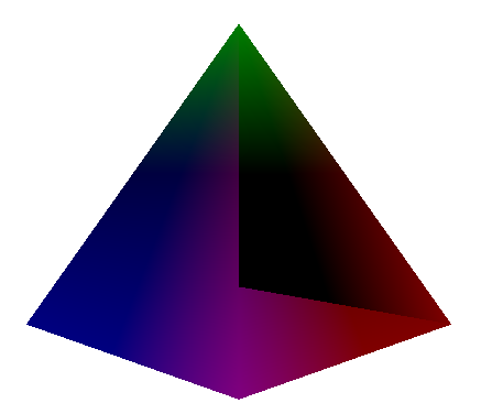
The final result can be seen below:
The end
This is the end of this part of the course. As usual - if something is not clear, please write comments underneath or contact me by email. I invite you to the second part, in which we will review transforms in a 3D world - there will be some movement on the screen! :-)
